Michael Hotka's
My New Telescope Construction
Rocker Base Progress Through September 10, 2006
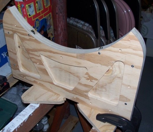
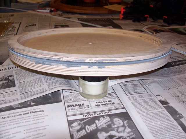
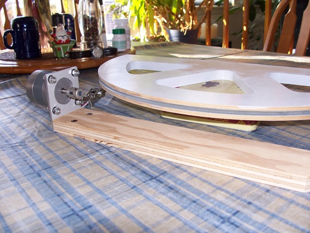
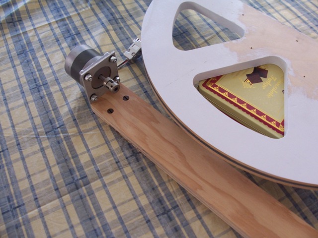
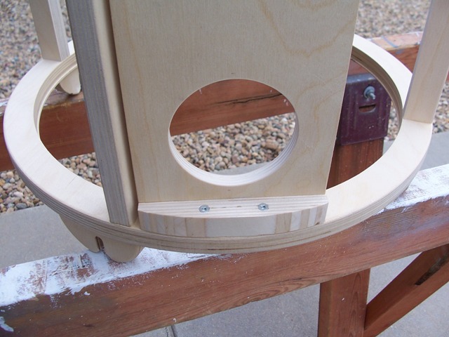
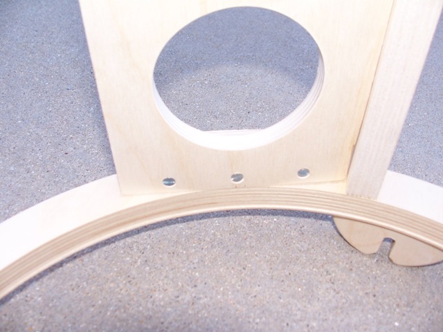
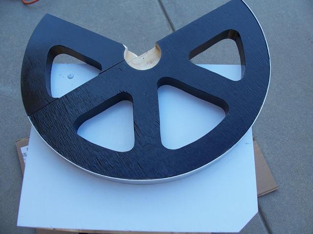
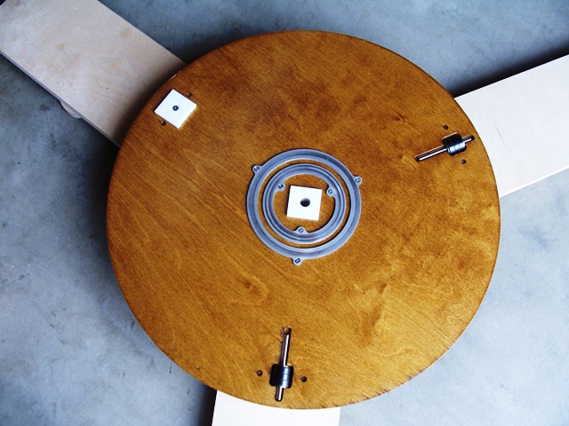
Making the Azimuth Gear
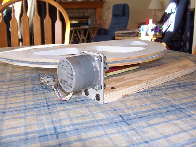
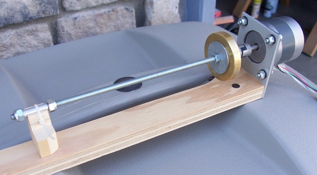
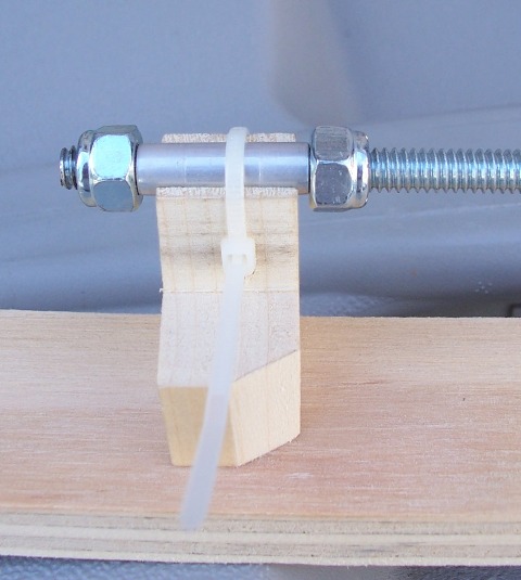
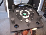
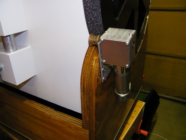
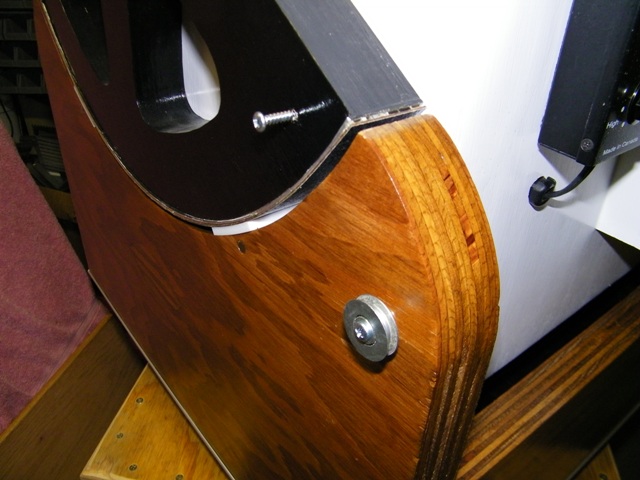
Motor Mounts and Orientations
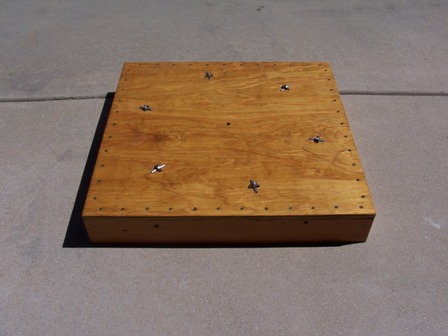
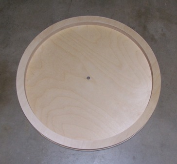
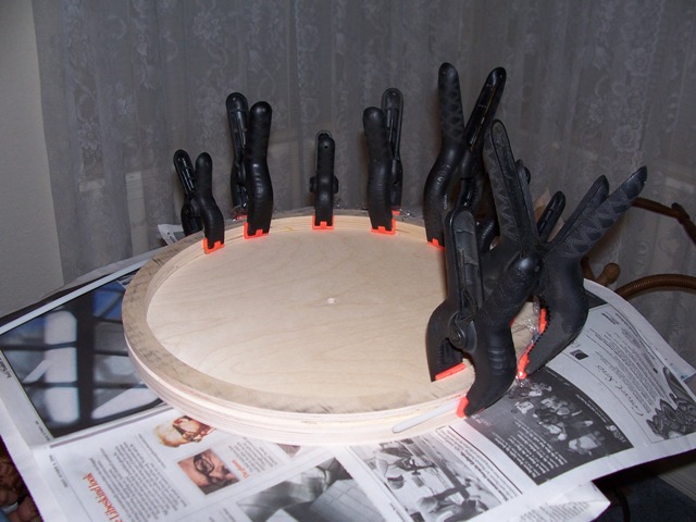
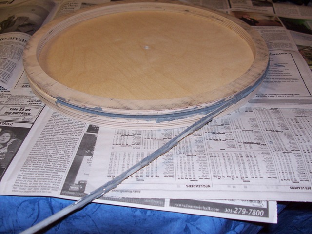
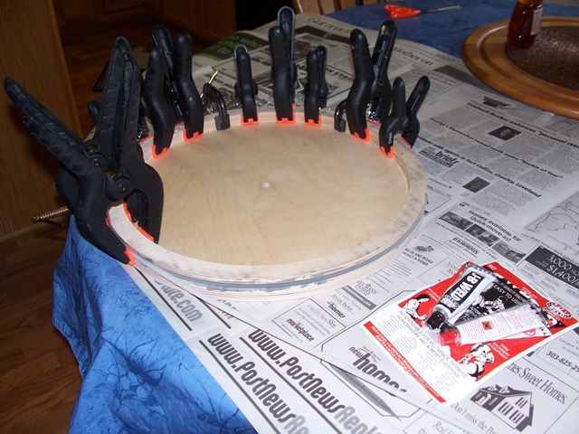
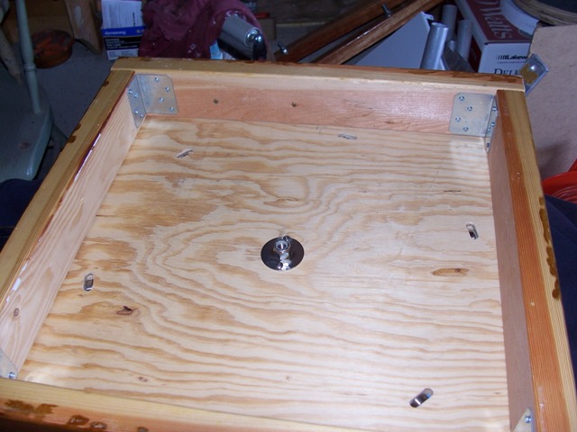
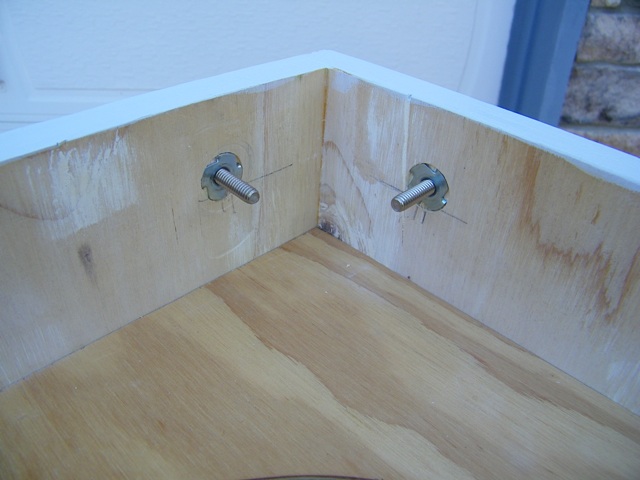
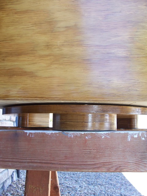
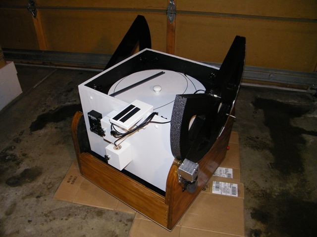
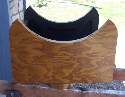
Ground Board that Fits - February 11, 2007
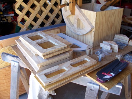
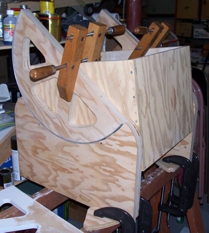
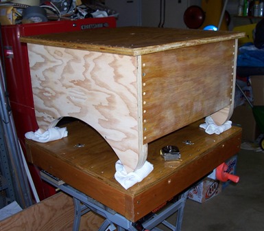
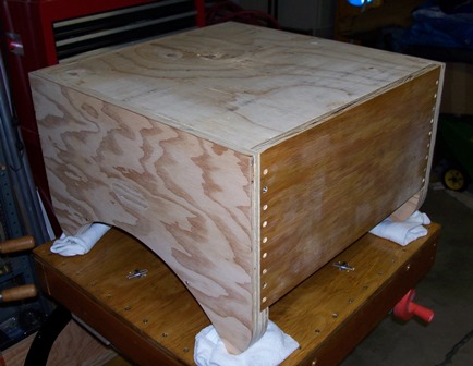
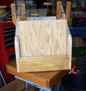
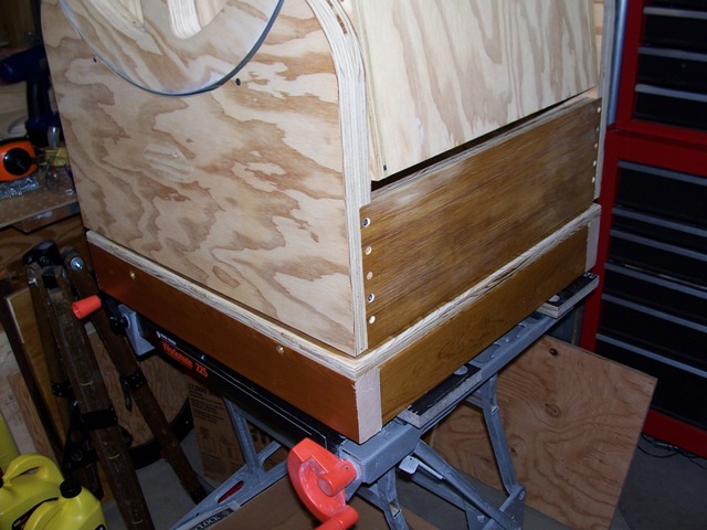
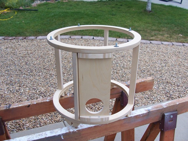
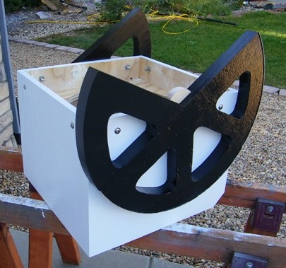
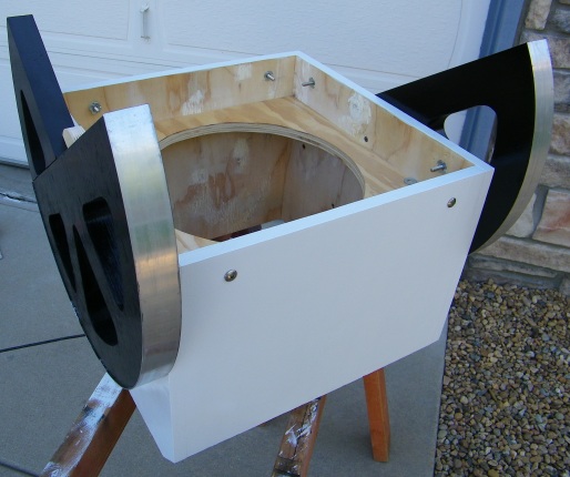
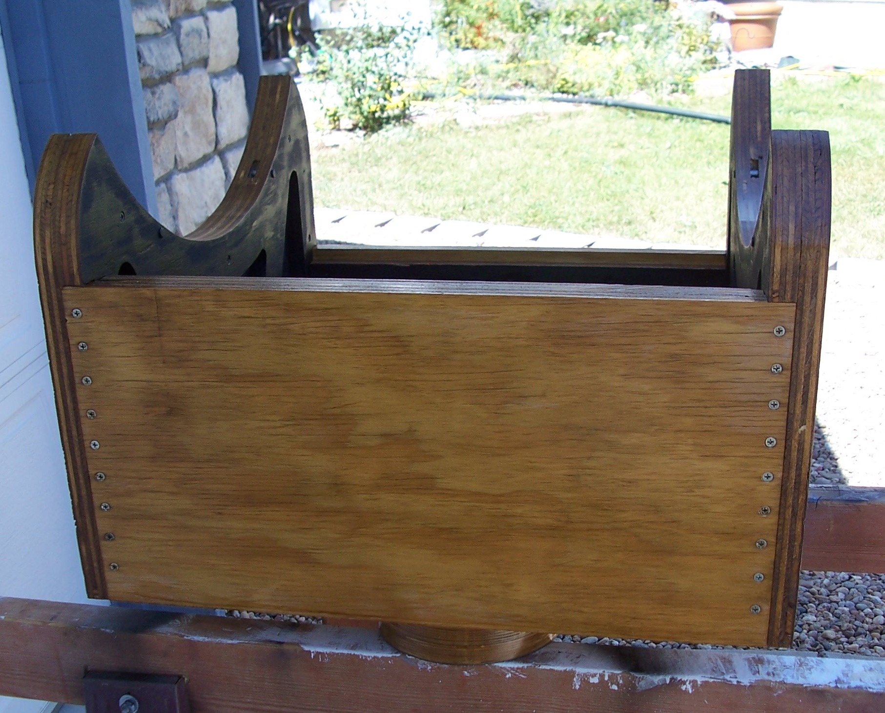
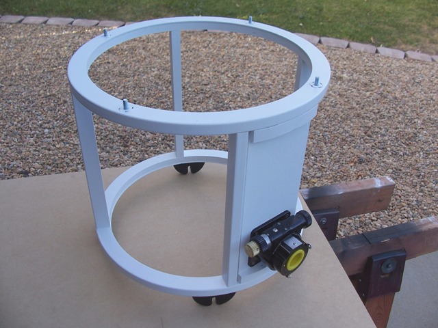
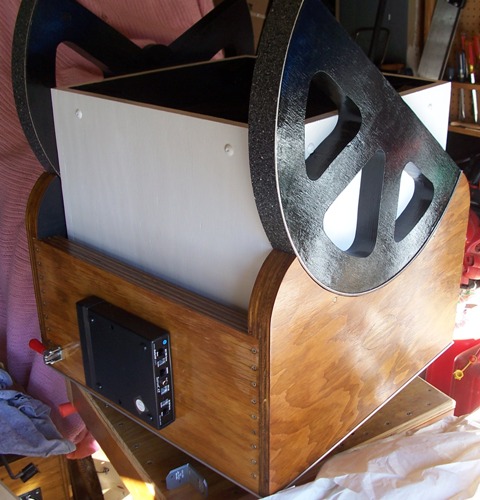
Rocker Base Taking Shape - September 27, 2008
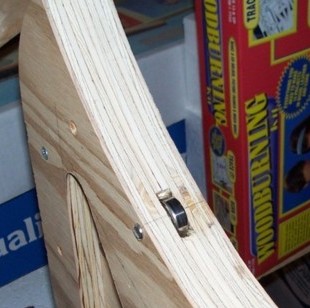
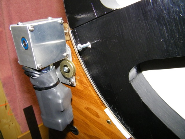
Reworked Motor Mounts with Thrust Protection - September 28, 2008
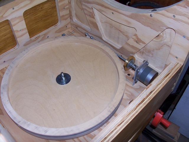
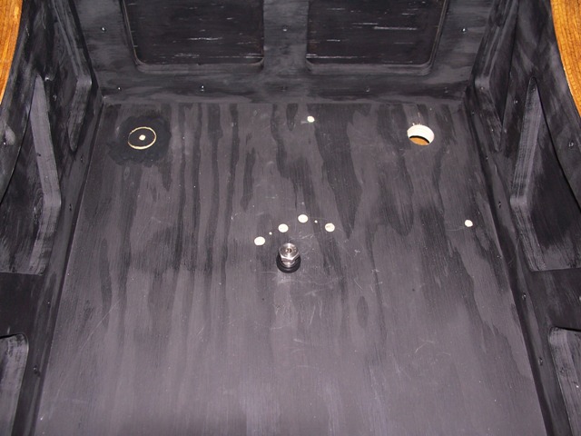
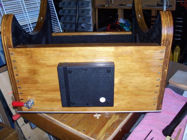
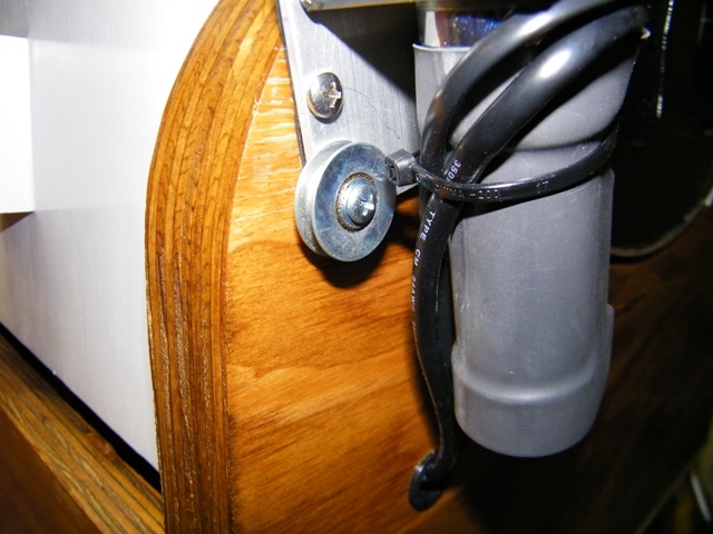
Azimuth Motor Mounted Inside Rocker Box Base - September 29, 2008
Met an old friend at the 2010 Texas Star Party who told
me his tale of adding
a Mel Bartel's controller to his telescope and how he was much happier
with his telescope control system when he upgraded to a ServoCat controller
with Digital Setting Circles.
So when I returned from the star party, I bought new parts
from Randy Cunningham
of Astrosystems in La Salle, CO - June, 2010.
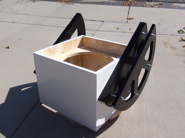
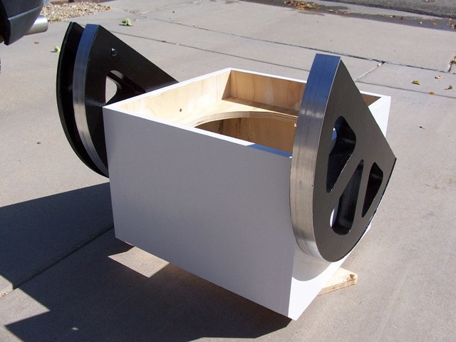
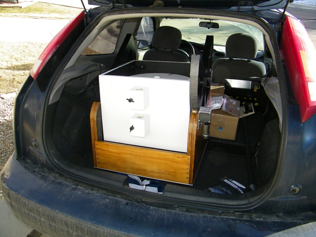
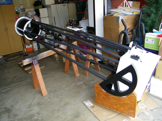
Basically overnight, the scope construction went from this:
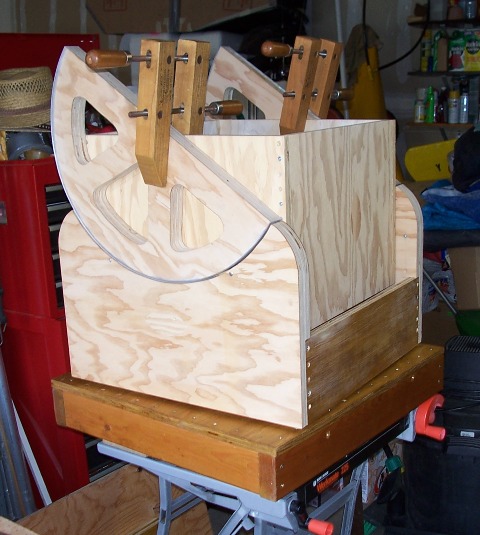
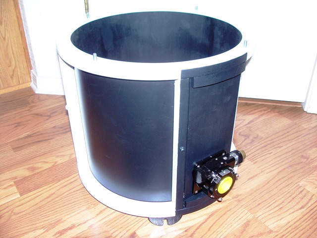
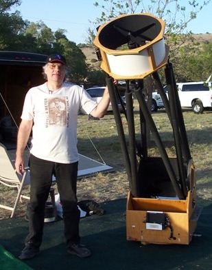
to this:
And the completion of my dream scope was finally in sight...
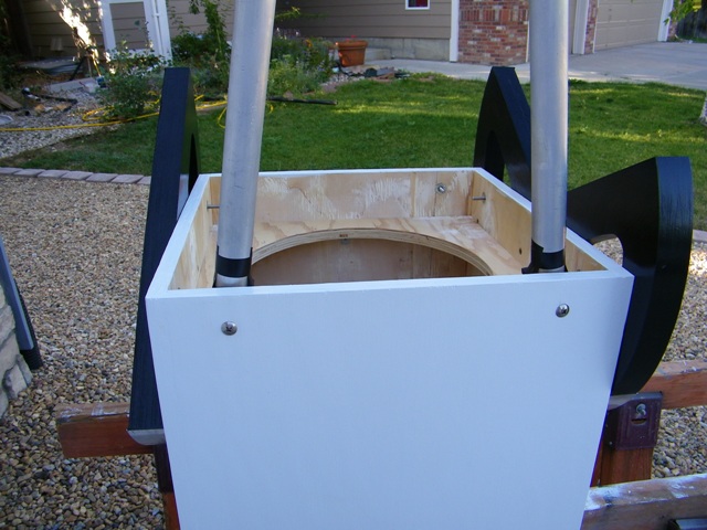
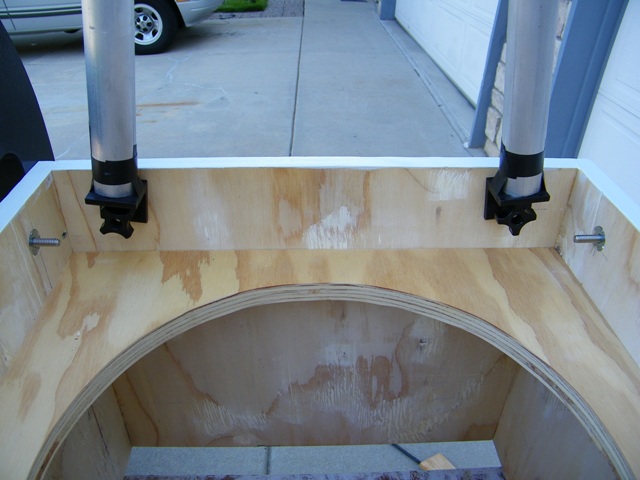
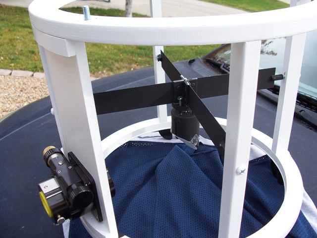
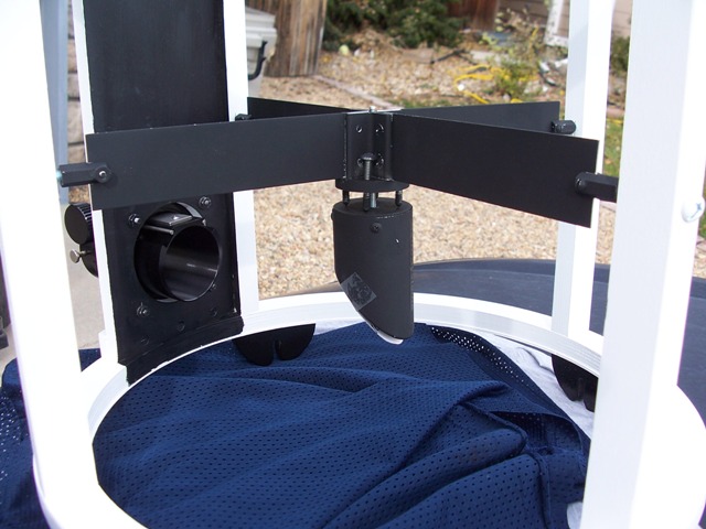
Upper Cage Assembled Attach Focuser Plate Not much clearance to get this bolt in Inside connector view Mirror cell with drive extension Connectors on mirror cell What it will look like done Corners almost touch.
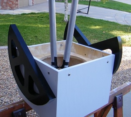
Measuring was critical to
fitting these into the
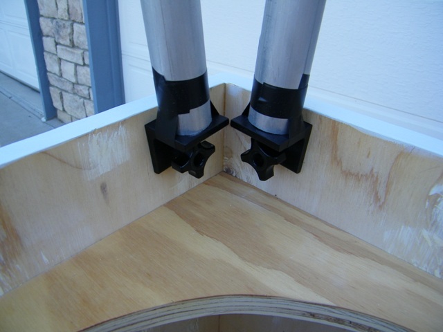
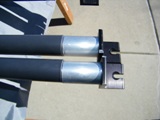
existing mirror cell.Another view from the outside And what it looks like on the inside. The black tape on the aluminum poles is temporary.
Progress Labor Day Weekend -September, 2010
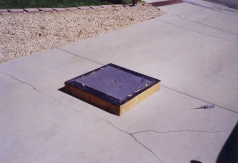
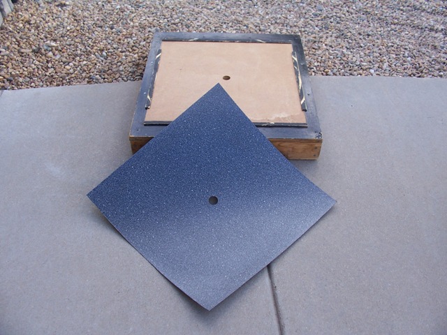
The Old Telescope
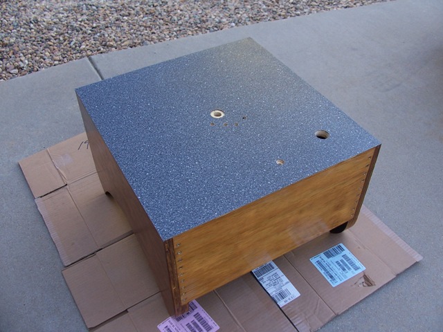
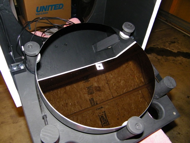
Ground BoardRemoved Ebony Star for
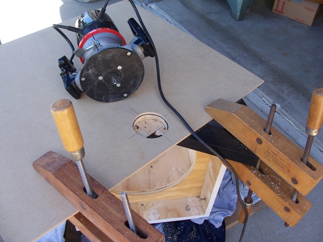
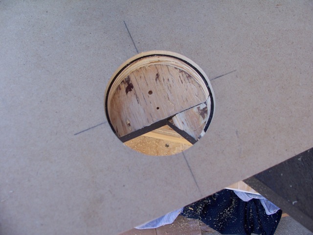
New TelescopeAnd put on the bottom of new rocker box. Needed to route out the
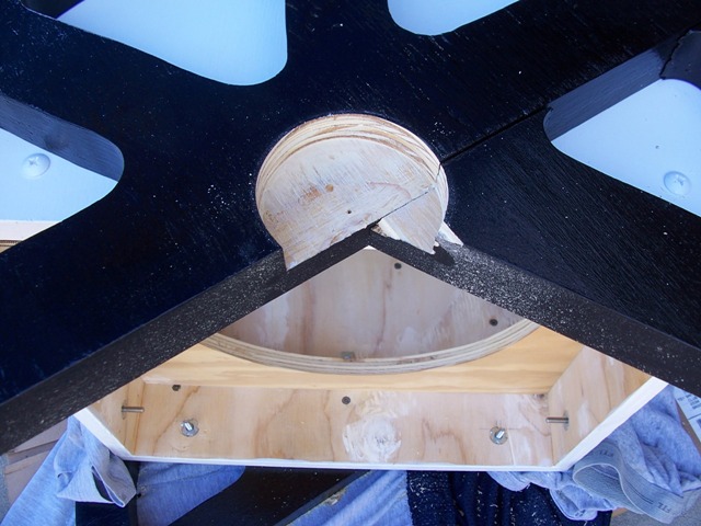
altitude bearing...to allow for a
protective recess for...the Altitude Encoder. Nicely done. Attaching the Gound Board
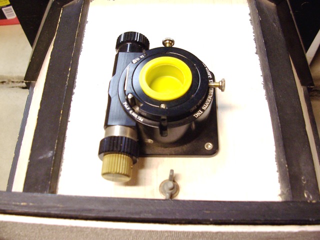
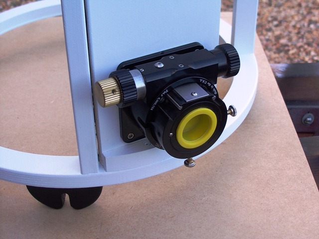
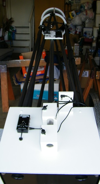
to the Rocker Box...on September 6, 2010. Holes for power transfer and azimuth motor Completed Power Transfer System Completed Azimuth Motor Installation Azimuth Encoder Transfer Focuser from Old Scope To New Scope
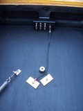
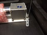
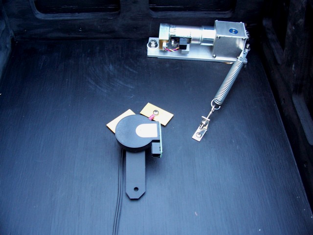
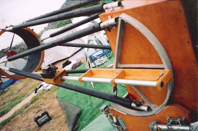
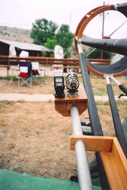
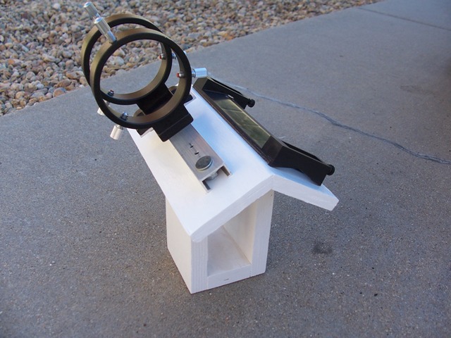
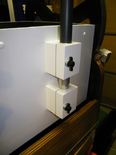
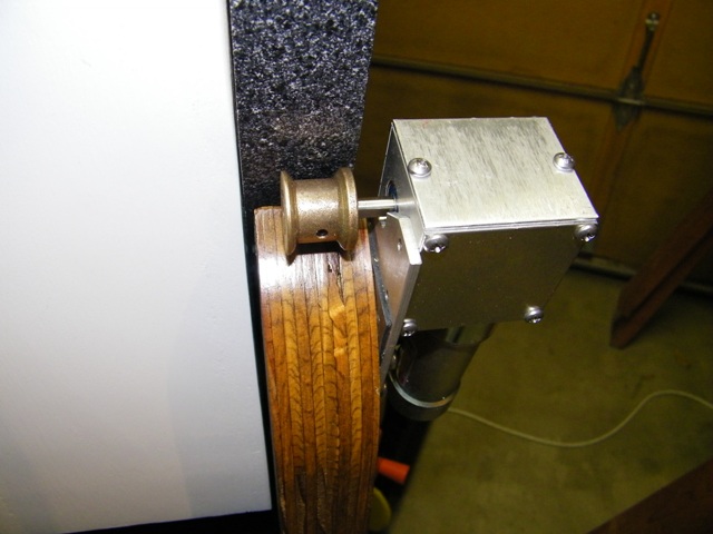
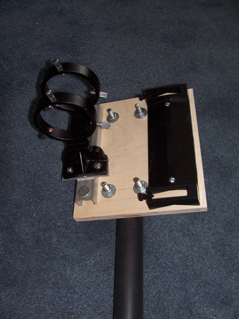
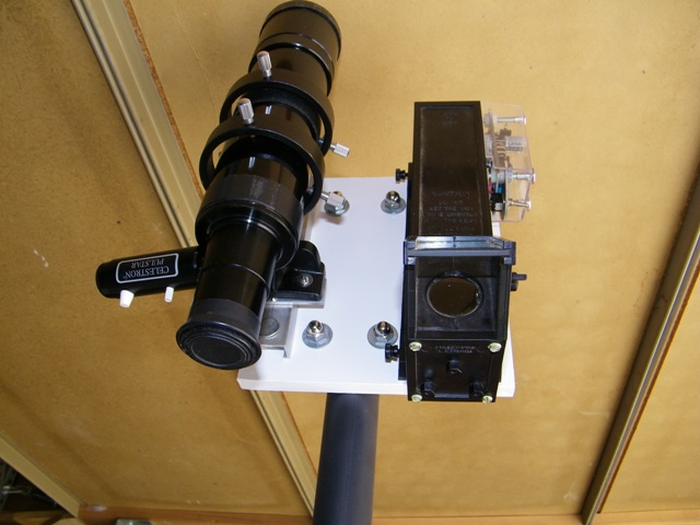
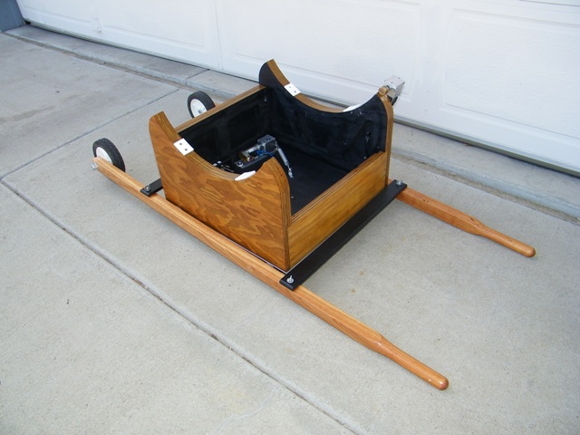
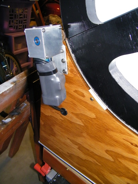
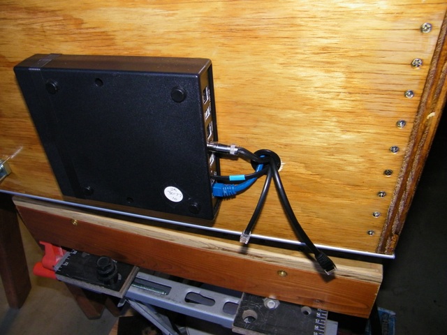
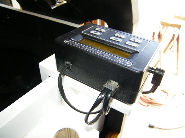
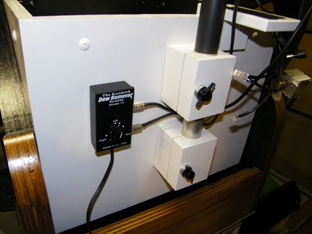
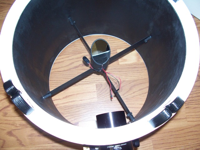
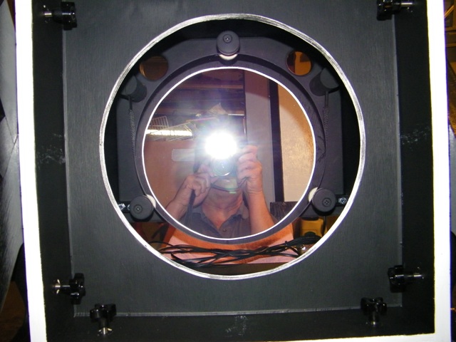
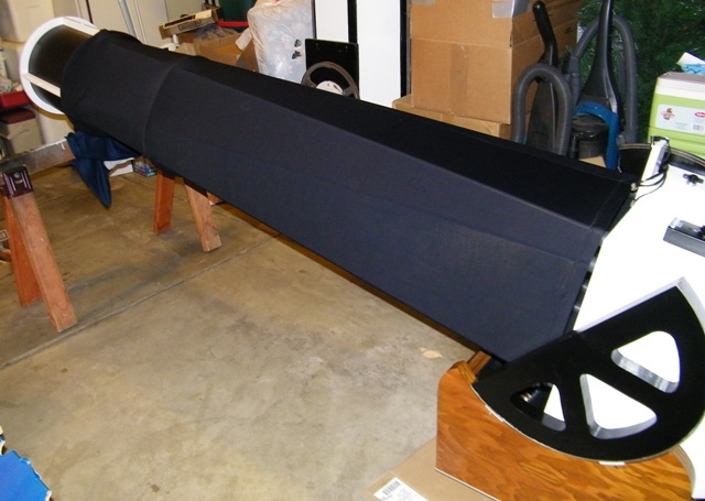
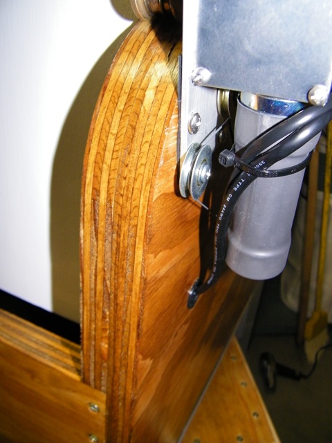
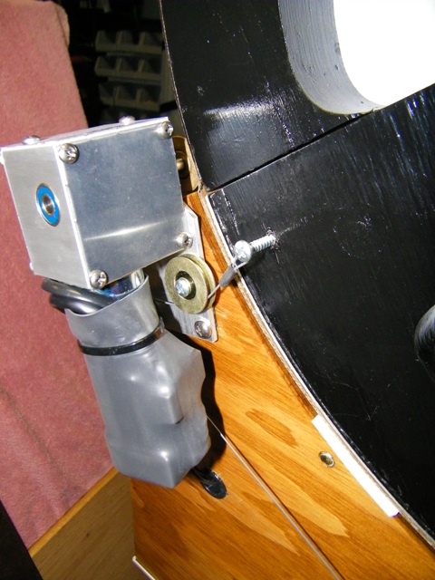
September 29, 2010Finder Scope Platform I saw on a scope at the TSP 2005 I want to replicate for my telescope. I like the idea of the platform at shoulder height and not adding the weight on the secondary cage. Picture evolution from old telescope's mirror cell to new telescope's mirror cell. My Finder Scope Platform. This proved to be too heavy. Mounted the Spider into the Secondary Cage. ServoCat Computer Mounted to Base Integrated Rocker Box with Base. Mounted Finder Scope Platform Clamps 1/16/11 Mounted Altitude Motor My New, Lighter, Finder Scope Platform. .Telrad and 8x50 Finder with illuminated cross hairs The Dolly to help move it around. Altitude Motor Wired. ServoCat Controller partially wired. Sky Commander Wired Dew Heater Controller - January 30, 2011 It barely fits in my car. Guess I won't be using it to take scope somewhere Finished Upper Cage Installed Secondary Mirror on 2/2/2011 All Together - 2/11/2011 Added New Mirror - 2/11/2011 Altitude Motor Engage Clamp Altitude Motor Pulley Assembled - 2/13/2011 With Light Shroud See More Pictures of Truss Tube Extension Spring Counter Balance Anchor - 3/1/2011 Other Altitude Bearing Anchor Cable Tucks Under Motor Added Springs 3/4/2011 Extra Length is Perfect How cable... ...snakes around motor. With all my careful calculations from the Tom Krajci's article, there was something wrong. The spring, that the calculations showed would do the job, showed some signs of counterbalance, but did not counter balance the scope. I was disappointed. (Later analysis showed I calculated the spring K value wrong. I had calculated inches per pound, INSTEAD of pounds per inch).
So, Barbara and I took a trip back to Iowa in early March, 2011 to see all our folks. My dad has always been a huge part of my telescope building efforts. In discussing the equations and the performance of the spring to counter balance my telescope, I found out he is a genius on levers, which is what this counter balance system is all about. He had great suggestions, which I implemented upon returning home, and the finished pictures are below.
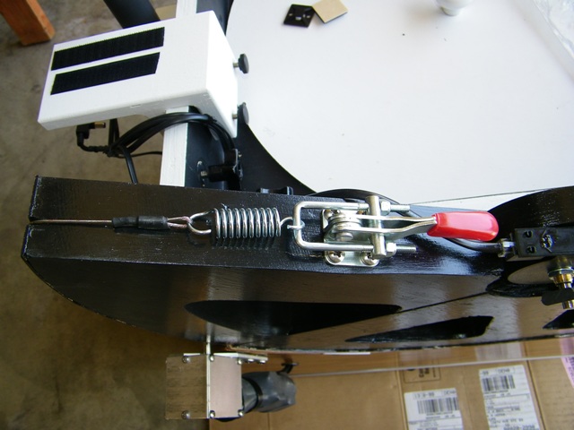
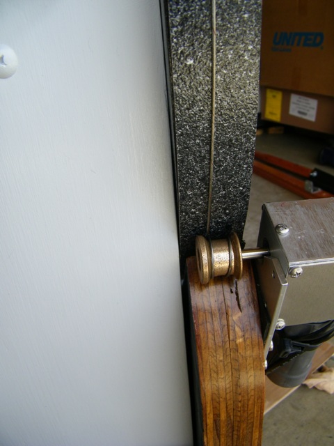
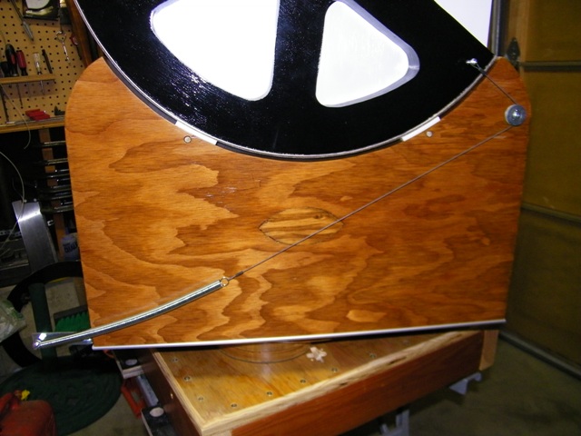
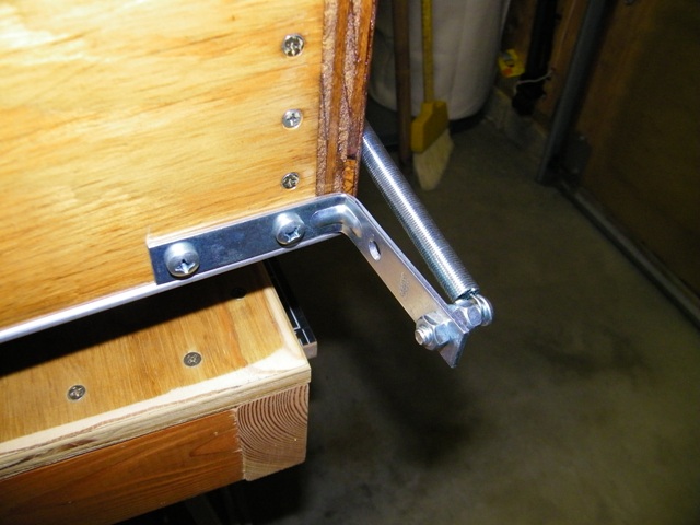
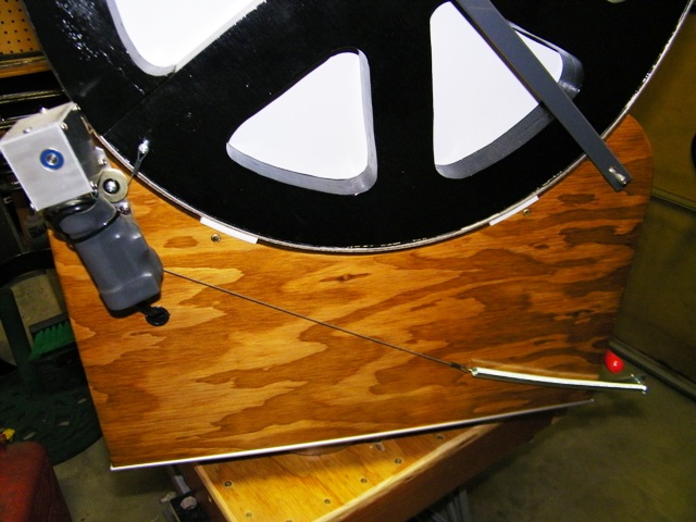
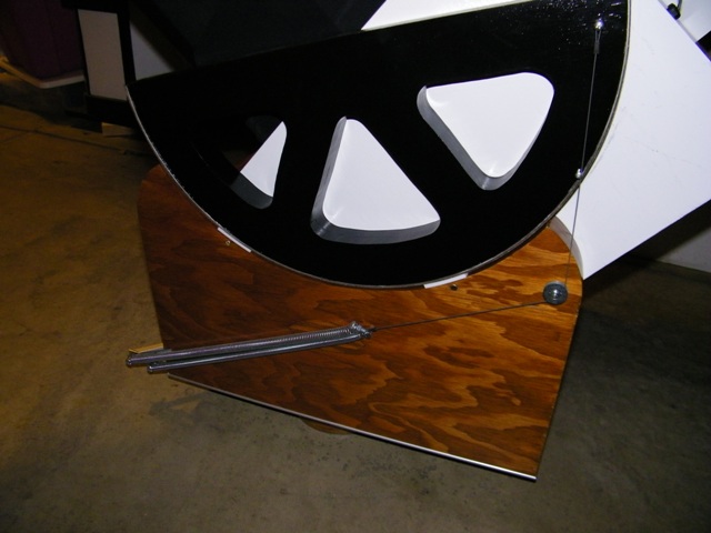
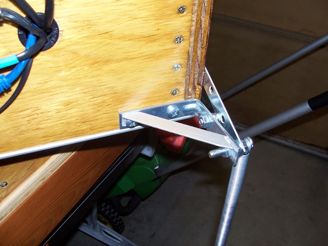
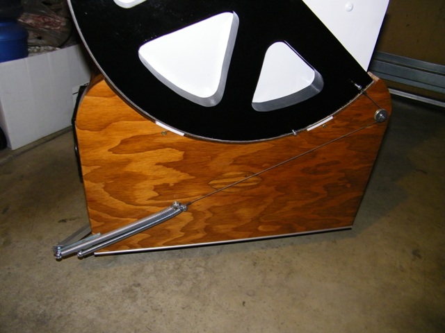
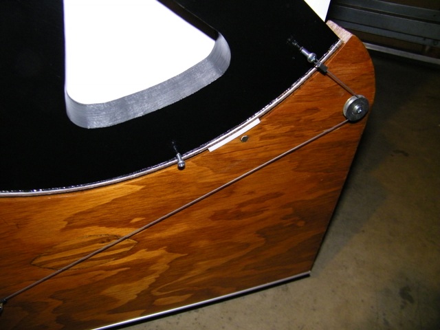
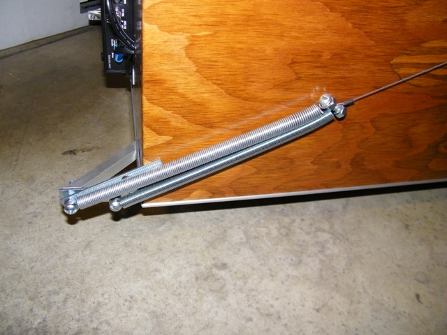
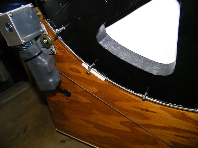
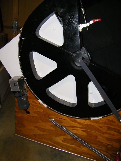
One thing my dad suggested is not to let the cable fold back on itself, basically rolling over the top. He indicated you loose a lot of work from the spring when you allow this to happen. At his suggestion, I added screws to catch the cable to keep the cable pulling the spring strongly. With these screws, the cable never rolls over the top and back upon itself. Also, I moved the screws out as close to the edge of the altitude bearing as I could, thus increasing the lever distance and getting more pull from the springs.
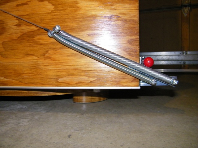
I needed two springs on each side to do the job. The lower spring is a .54 gauge wire spring and the upper spring is a .63 gauge wire spring. Together, with an identical set on the other side, the scope is now balanced in all angles of altitude. The combined K Value for each set is 3.32. With the guide pin distance I choose, each set of springs yeilds 476 in-lbs of force, more than enough to balance the 10 lb, 900 in-lb, downward force at the very front of my telescope.
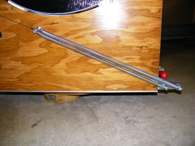
Below are more pictures of the finished spring system on March 31, 2011.
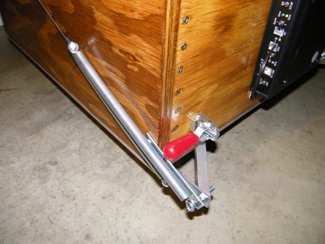
I needed to brace the spring anchor bracket to support the stiffer springs
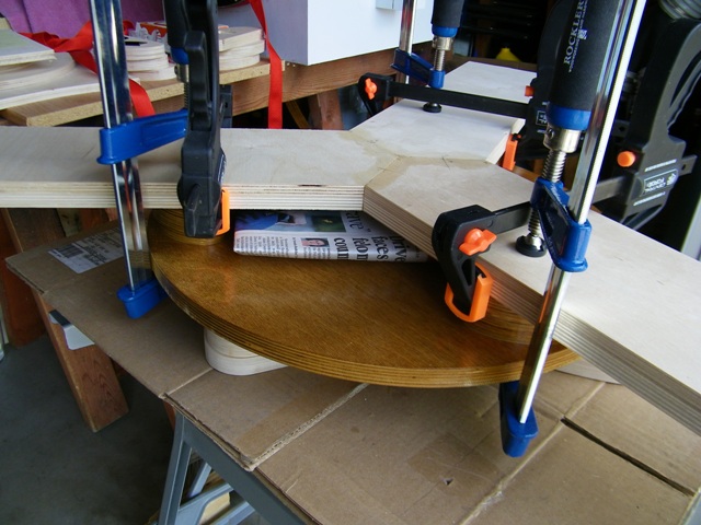
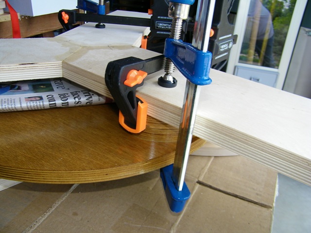
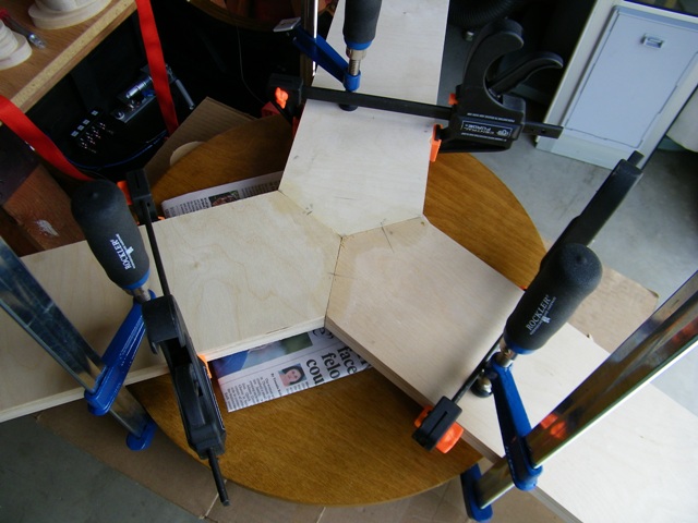
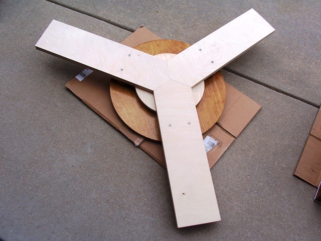
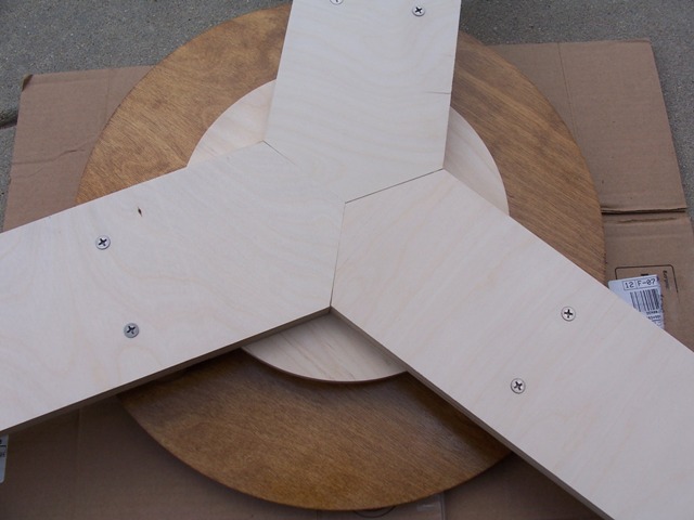
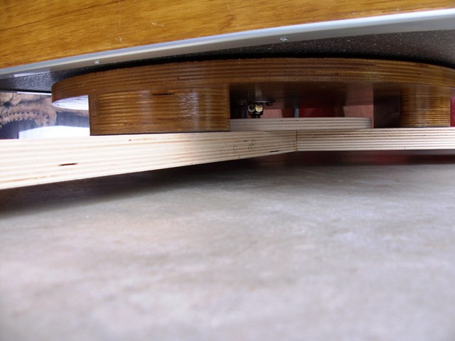
Double springs relaxed with telescope pointing verticle Closeup showing screw to catch cable to keep the spring doing maximum work Closeup of double springs Cable catch screws on other side of scope Springs attached to anchor Telescope at 45 degrees altitude showing springs extended and cable catching the screw Cable catches on other side of scope. Double springs stretched, keeping the scope in perfect balance What I have found with my long focal length and 90 inches of truss tubes and upper cage, that the scope is now a bit tipsy when it is pointed more than 45 degrees towards the horizon. Randy Cunningham suggested to make a bigger foot print at the base. So I glued up these pieces of wood, ensuring that they are directly over the existing base feet. This is so that when I attached this stabilizing base to the existing base feet, all the wood lines up nicely. I added a stiffener piece to help strengthen the joint. See the pictures below:
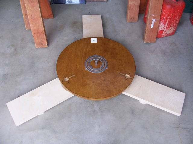
I biscuit jointed these pieces together Ensuring the base is directly over the existing feet Another view from the top Makes a bigger footprint to remove the tipsiness of the scope Turned out real nice. From below. I will test the system in the field, adjusting the stabilizing base feet until I have the tipsiness out of the system. Then I will permanently attach these feet to the stabilizing base and finish the wood.
Back to Main Astronomy Page